Process Templates
Process Templates are the intelligence blueprints of the RCOM Agent. They define how edge devices (RFID readers, sensors) capture data, how that data is processed locally, and where it is eventually sent. By using a visual, no-code designer, you can standardize complex edge operations across hundreds of agents with a single deployment.
Once created, a single template can be reused across multiple agents, ensuring consistent, centrally managed behavior.
Understanding the Designer Interface
To begin, navigate to Agents → Process Templates from your RCOM dashboard. Click + New Template to open the Visual Designer.
- The Component Library (Left): Your toolbox containing Devices, Services, and Functions.
- The Canvas (Right): The workspace where you drag, drop, and "wire" your logic.
- The Properties Panel: Accessible by clicking edit on any component or connector to configure its specific parameters (e.g., IP addresses, timers, input, output).
The Building Blocks: Components
| Component Type | Role | Technical Rule | Example Use |
|---|---|---|---|
| Device | Interfaces directly with Auto-ID or IoT hardware (RFID, Barcode, etc.) | Must connect to a Service or another Device. | Siemens_RF6x_V1, Multiplexer_V1 |
| Service | Data Handling Layers (Read-points, Buffers) | Can connect to any other component type. | Readpoint_V1, BufferedSender_V1 |
| Function | Data Transformation & Egress (API, Formatting) | Cannot receive data directly from a Device. | TagForward_V1, WebRequest_V1, TagFormatCrossTalkJson_V1 |
RCOM uses a modular architecture. A valid template must begin with a Device module to act as the data entry point.
Each module in the RCOM Agent acts like a circuit component with defined "ports" for data exchange.
-
Data Points (Ports): Every module has predefined input and output data points. These are structured interfaces that act as the "entry" and "exit" ports for information.
- Example: A
ReadPointmight have 2 inputs and 2 outputs to manage separate streams for tag data and reader status simultaneously. - Example: A
TagForwardmodule might have 1 input but 5 outputs to handle different delivery results (e.g., Success, Timeout, or API Error).
- Example: A
-
Output Variables: These are the specific, named identifiers assigned to the data leaving a module. Other components reference these names to "grab" the data they need.
Step-by-Step: Building Your Process
Step 1: Add and Configure Components
- Drag a
Devicemodule (e.g.,Siemens_RF6x_V1) onto the canvas. - Configure its connection parameters (IP, Port) in the properties.
- Add a
Service(e.g.,Readpoint_V1) to manage the capture logic. - Add a
Function(e.g.,WebRequest_V1) to define the final data destination.
A device should only connect with the
Serviceor anotherDevice. It cannot connect directly to aFunction.
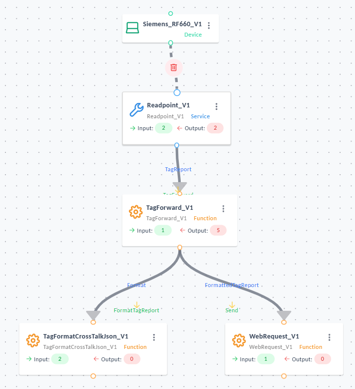
Example Process Template
Step 2: Linking with Smart Connectors
Connectors are more than just lines; they are the "translation layer" between modules. Click an output port of one module and drag it to the input port of the next, creating a "handshake" that defines how data moves between blocks.
- Output: Selects the output schema of the upstream block, determining the data structure the connector receives.
- Input: Specifies the input schema expected by the next processing block.
- TimeoutInMs: Sets the maximum time (milliseconds) the connector waits for the next stage. Exceeding this triggers an internal timeout error.
- Optional Temporary Variable Assignments: Allows you to create temporary variables that can be used within this connector. These variables exist only during this connector execution and are not persisted beyond it.
- Optional Custom Script – Pre-Call: Executes custom script logic before invoking the next module.
Common uses:- Adjust field values
- Apply conditional formatting
- Clean or normalize tag data
- Enrich payload with custom logic
If left empty, the connector forwards data untouched.
-
Optional Abort Expression: Defines a conditional expression that, when evaluated to true, aborts execution of the connector.
Typical examples:deviceId == nullrssi < -80location == "UNKNOWN"
-
Required Parameter Mapping: This section displays the input parameters required by the next processing module, and lets you map them from:
- Dynamic values (existing incoming fields)
- Static values (manually entered constants)
Each row includes:- Name: The name of the parameter required by the target processing block.
- Variable Type: Indicates expected type. This helps ensure correct mapping.
StringNumberBooleanDirection(custom enum)List<String>or specialized listsBoolean?, etc.
- Static / Dynamic: Defines how the parameter value is supplied:
- Dynamic → mapped from an incoming field such as
deviceId,timestamp, etc. - Static → manually set constant such as
"enabled"or"true"
- Dynamic → mapped from an incoming field such as
- Is Null: Specifies whether the parameter is allowed to be null. If disabled, a missing value will cause a validation failure.
- Value: The actual source value:
- When Dynamic, you provide the name of one of the incoming fields.
- When Static, you enter a constant value.
-
Optional Custom Script - Post-Call: Executes after the connector processing completes.
Useful when:- A final transformation is needed
- Additional logging or filtering must occur
- You need to validate the downstream result
If left empty, no post-processing occurs.
- Return Values Mapping: Defines the output values that the following module must return to the preceding processing block. Return values are only applicable for selected blocks that have a return value.
These values are forwarded into the next block using the schema selected under Input.
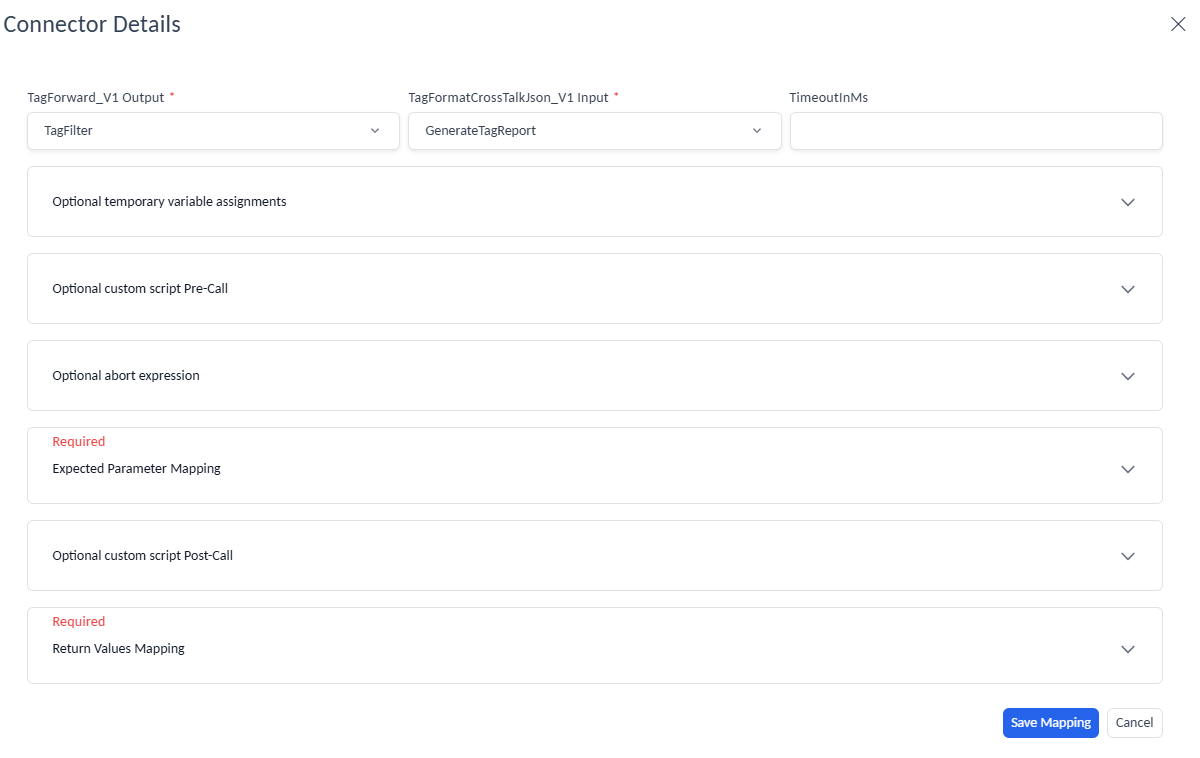
Example Connection Configuration
Step 3: Validate, Save, and Activate
- Once all module connections are valid, click Next → Save Template.
- Review metadata such as template name, version, and release notes.
- Set Status = Active to make the template available for assignment to agents.
Active templates can now be applied under Agent → Processes.
Define Template Variables
At the bottom of the Template Designer, click Manage Variables.
Template variables allow you to define dynamic values (e.g., device IPs, URLs, topic names) that can be reused across Components.
Using variables simplifies maintenance and makes templates portable between environments.
Managing Existing Templates
The Template List displays all configured process templates along with version and status details.
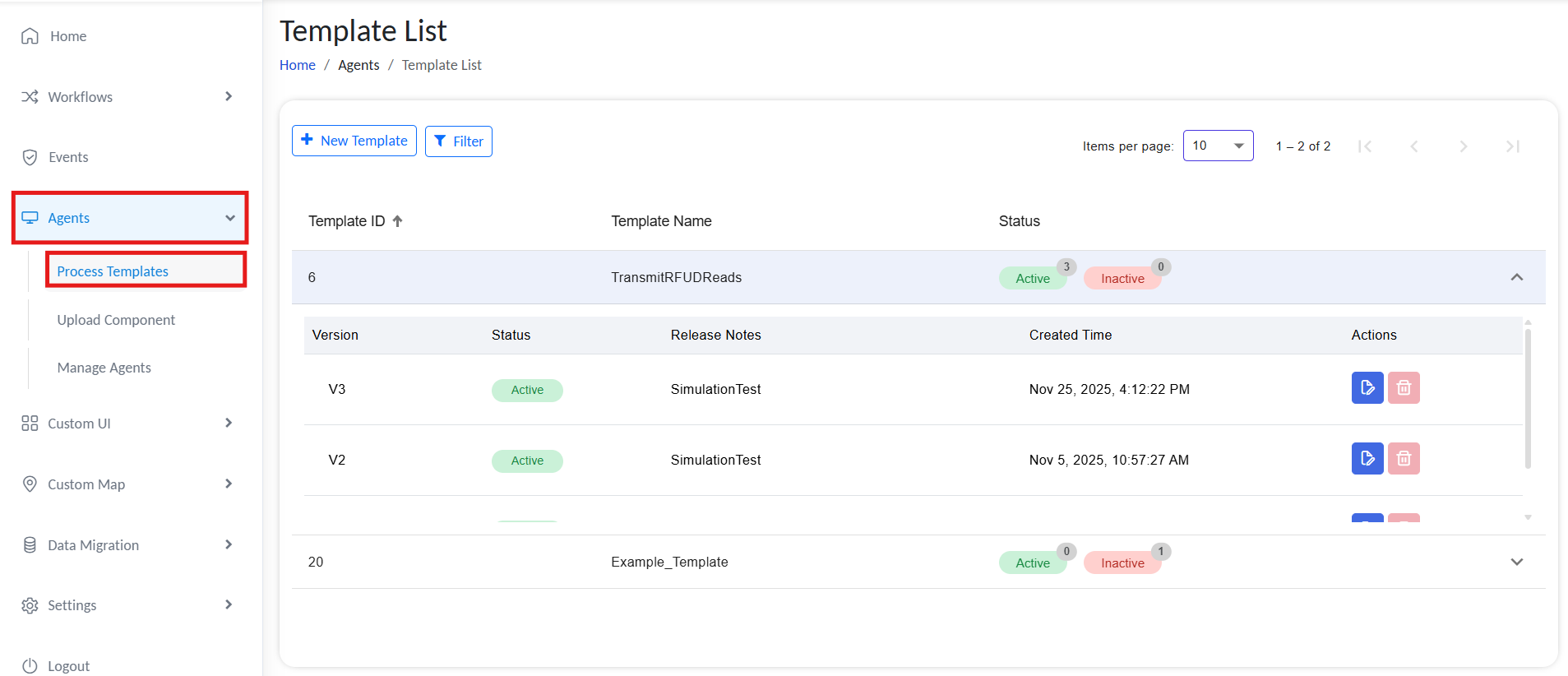
Manage Process Templates
From the Template List, you can:
| Action | Description |
|---|---|
| Edit | Open the template in the designer to modify the flow or parameters. |
| Version Control | Select which version of the template you want to be active. |
| Delete | Permanently remove a template no longer in use. Ensure it’s not assigned to any agents before deletion. |
Best Practices
- Keep device-specific parameters as variables to improve portability.
- Maintain version notes to track changes across template updates.
- Validate all module connections before saving to avoid runtime issues.
- Regularly review and deactivate obsolete templates to keep the system clean.